Lightweight Access Point Protocol (LWAPP)
Introduction
LWAPP is Cisco's proprietary protocol used to provide central control of Access Points.
With LWAPP, the AP automatically detects the best available Cisco Wireless LAN Controller (WLC) to download
appropriate policies and radio and SSID configuration information with no hands-on intervention.
Normally a switch that receives frames from a wireless client A (via an AP) would forward the frm to the destination client B.
In the LWAPP scenario though we need this frame to go first to the controller. In order for this to happen
LWAPP adds extra headers to the frame. In Layer 2 mode LWAPP uses a layer 2 header IF the controller
is in the same LAN so that the AP does not need an IP address. In Layer 3 mode LWAPP uses a layer 3 header
AND a later 2 header. The controller could be in the same LAN or a different LAN. The layer 3 header
contains the destination IP address of the controller, the source MAC of the AP and the destination MAC of the router.
AES encryption and Counter Mode with Cipher Block Chaining Message Authentication Code Protocol (CCMP) is used
for the LWAPP Control traffic.
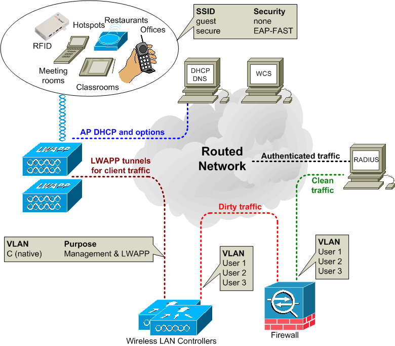
The operation of LWAPP is described in line with the topology diagram above. The client device connectivity occurs as follows:
- When the AP initially connects to the network it broadcasts at layer 2 looking for a controller.
This is a LWAPP Discovery Request that should be received by the controller management MAC address.
What should happen is the controller ought to respond with a Discovery Response indicating
the number of APs associated to the controller. The AP then connects to the least loaded controller
by sending a Join Request.
- If no controller is found at layer 2, then the AP requests an IP address via DHCP.
- If a controller is not found on the same subnet then the layer 3 switched network
often deploys DHCP relay on the VLANs that the APs use.
The DHCP server not only responds with an IP address but it also provides the AP with the IP addresses of available
WLCs (Option 43, sub-option 241), these addresses may be prioritised with one Wireless LAN Controller (WLC) being first
and another WLC second. The default gateway and DNS information is also provided by the DHCP server.
- In layer 3 mode the AP sends a LWAPP Discovery Request to the AP manager IP address using a directed broadcast.
- If there is no response then the AP will send the Discovery Request to any controllers that have been learned
from other APs via Over The Air Provisioning (OTAP).
- The controller responds with a Discovery Response indicating
the number of APs associated to the controller.
- The AP then sends to the least loaded controller a Join Request which contains the AP's X.509 certificate.
- The AP uses the following order when associating with a controller:
- First try the Primary controller, then the Secondary and then the Tertiary controller.
- Next try the Master Controller
- Then the least loaded controller
- Finally, the least loaded Access Point Manager interface
- The WLC validates the AP and then sends an LWAPP join response to the AP and this contains the WLC's X.509 certifcate.
- The AP now validates the WLC, thereby completing the discovery and join process which includes mutual authentication
and encryption key derivation using the X.509 certificates. This is used to secure the join process and future LWAPP control
messages.
- The AP registers with a WLC according to hardware option 60 parameters that describe the hardware AP type.
- The WLC updates the AP image software if required and configures the AP with the appropriate radio and SSID settings
- A client device attempts to connect to an SSID.
- If 802.1x authentication is required then credentials are sent through the LWAPP tunnel to the WLC.
- The WLC maps the SSID to the relevant user VLAN and this 802.1x traffic enters the firewall.
- The firewall rules permit this traffic to be forwarded on to the RADIUS server. The RADIUS function may be provided by
Cisco's ACS (Access Control Server).
- The RADIUS server checks the credentials and allows the user device access.
- The user device now obtains an IP address via DHCP through the firewall.
- The corporate policy determines where the user can go and what that user can do.
- For the SSIDs that use WPA2-PSK for encryption, there are different network keys set up on the WLCs for each SSID.
Users must use the relevant key to gain access to their SSID.
LWAPP uses the UDP source port of 1024 and the destination port 12222 for the data traffic and
UDP source port 1024 and UDP port 12223 for the control traffic.

|
