Content Networking
1. Introduction
This document looks at the issues and technologies surrounding Internet and Intranet traffic.
More and more organisations are relying upon web-enabled applications to deliver resources and
'Content' to the end-user. Web-sites and Intranets are becoming more essential to organisations
so that not only is reliable data delivery very important, but also the user-experience of that
delivery has to be of the highest quality.
HTTP is typically used as the navigational protocol, which then leads to other protocols such
as FTP and RTP being called into play.
The HTTP protocol is specifically discussed in HTTP, so use this for reference.
2. Issues
A user who has to wait for too long for a page to load
will more likely find some other site to visit. Studies have shown that a person will
wait for a maximum of 5-6 seconds before giving up on a page loading.
Another issue with web content is that it is continually changing and increasing in volume
(an estimated 700 million on line by 2005!). The very nature of the web is such
that users are encouraged to revisit regularly, that they can contribute and interact and this leads
to a very fluid and flexible information base. The type of data varies too, from traditional text-based information,
through to pictures, photographs, sounds, music and videos.
The impact on network bandwidth usage is increasing and therefore needs to be quantified and managed.
This management of the traffic can then lead to Service Level Agreements (SLA).
Difficulties facing those managing the include problems such as Flash Crowds where unexpected large
numbers want to access one particular piece of data or news e.g. September 11th 2001 on the CNN website.
Typically this applies to 10% of web site content. Other problems
include Denial of Service (DoS) attacks on a website, a typical web server can only cope with up to 2,500 SYN requests per second.
Lost shopping carts can occur when users change servers half-way through a transaction. This can happen because
their ISP changes their IP address during the transaction.
There is an issue called Distance Delay which can be illustrated with the simple example of the speed of light.
Between San Francisco and New York it takes 0.7 seconds for electrical signals to travel in optimum conditions, however
between Melbourne and New York it takes around 2.5 seconds. Bearing in mind that TCP requires a three-way handshake, you can see that
response time starts to get sluggish the further away the client is from the server and therefore the content. On top of this
delay you have the complication of the packets travelling through multiple routers and NAPs (Network Access Point).
Web traffic tends to consist of 'Short Flows' which consist of data transfers less than 15 Kbytes, and these flows are identifiable
by their source and destination IP addresses and their Source and Destination Ports. A user's browsing experience can very easily
consist of many short flows at any one time.
These flows may be requesting alot of information from many destinations. To try and ease the load on a server a switch is introduced
to share the traffic across a group of servers. This is traditional Server Load Balancing (SLB).

The issue with this is that
you cannot guarantee which server a client will use, so content has to be replicated on each server taking part even if the switch
is intelligent enough to understand layer 4, HTTP traffic is only going to distributed evenly without discretion.
3. Content Switching
A Content Switch can be used to make decisions based on the HTTP header information i.e. at the IP application layer.
This information includes the URL, cookies for sticky connections (bring clients back to the same servers),
file extensions (e.g. .de for German speaking users) etc.
Traffic can be prioritised based on the header information and QoS applied, this is called Header Load Balancing.
A major benefit of being able to make decisions based on the HTTP header is that content can be cached at strategic points
in the network. Rather than have clients pull popular content from a server located a long way away, the content could be
cached more locally to the client. Not all content is cacheable e.g. CGI scripts which rely on other external files
that modify parameters. AVI files, on the other hand ARE complete in themselves and they are therefore a popular choice
to be cached on account of their typically large sizes. Content switches can now decide whether certain HTTP Requests
should be directed to the actual servers or to caches instead. This can relieve the pressure on network bandwidth usage.
The order of events showing how a Content switch can provide protection and better
load balancing is illustrated in the following diagram:

The Content switch can now decide which least loaded server to use. ONLY when a particular URL is seen being
requested on VLAN 1 does the switch create a separate TCP session on VLAN 2
and 'snap' the flow together between VLANs 1 and 2. This protects the servers from DoS attacks.
The decision as to which server to use is then based on content rules such
as the URL, rather than just the port or IP address.
A Virtual IP address (VIP) is used on VLAN 1 to represent the URL.
Some Content switches can cope with many billions of hits a day thereby making it impervious to DoS attacks.
4. Caching
4.1 Overview
As well as load balancing across the servers at the server end of the system, we also want to minimise the traffic
load on the links that connect the clients to the servers. If the clients are requesting the same content regularly
it makes sense to have a 'send once' design to the content network. The job of the cache at the client end is
to locally cache content as and when it is found, and to serve the content to the client without the requests
hitting the WAN links unnecessarily.
Caching occurs at several locations across an internetwork, for instance the client itself generally caches content
on its local hard disk. Caching often occurs on the client's local LAN either transparently or on a Proxy cache.
Caching is often setup at the server end as well to take load off the web servers. As the content traverses the
network it can be cached en route in a hiearchy of caches, generally the aim being to minimise bandwidth usage.
Caching brings the benefits of better response times, reduced Internet traffic and network bandwidth usage, plus
it eases the load on network devices such as servers. The WAN links can then be utilised for other applications
such as voice and video.
There are some instances where caching certain content is not desirable, for example stock market prices, adverts or weather
pictures, where frequent changes are occurring to the content. In HTTP 1.1 the cache-control header is used
by the server to flag up how to deal with particular content. The cache engines and the client machines need to
understand the directives within these headers and abide by them. Generally, graphic, video and audio files tend to
be cached whereas pure text and HTML files are not.
The Internet Caching Protocol (ICP) as described in RFC 2186
and RFC 2187, is now quite old technology. Using ICP queries,
hierarchical and distributed caching architectures can be developed.
4.2 Content Freshness
How fresh particular content is can be determined by a number of headers. The
If-Modified-Since: header includes a date. If the requested resource has not been
modified since the time specified in this field, a copy of the resource will not be returned from the server.
The Expires: header gives the date and time that the message data should expire and is set by the server.
In addition, the Cache-Control: header has an option called
max-age that can be used in place of the Expires: header to determine when content is stale.
Finally, the Last-Modified: header includes a date
when the sender thinks the resource was last modified. If the recipient has a copy of this resource
which is older than the date given by the Last-Modified field, that copy should be considered out of date.
To decide whether a Response is fresh or not the concept of the Freshness Lifetime is used. The Freshness Lifetime (or Factor)
is equal to the Max Age Value if this has been included as a directive in the
Cache-Control header, otherwise it is the difference between the Expires value and the Date value.
If an object's header does not include an expiration time for that object, then
cache engines can compute the expiration time for each web object before they are saved to disk.
This calculation is (Today's Date - Last Modified date) x Freshness Factor.
A cache can re-validate content where the Freshnesss Lifetime has expired. The cache can do this by
sending a If-Modified-Since (IMS) request which grabs a fresh object from the server.
Refer to HTTP for detail on the HTTP protocol.
4.3 Web Cache Communication Prototol (WCCP)
Cisco developed WCCP to enable Transparent Caching throughout the network without using traditional HTTP Redirects.
Version 1 was limited to liaising with only one router, did not support multicasting
and was limited to HTTP traffic. WCCP v2 is the one to use now and is the one that we concentrate on here.
WCCP uses UDP port 2048 and operates over a GRE tunnel between the WCCP router and the cache.
Transparent caching is when a router redirects requests to a content engine, the HTTP packets remain unchanged within the
GRE tunnel. The destination IP address is different
from the IP address of the content engine. The URI is normally in the server-style which means the protocol and host name
of the destination are not present. The content engine could also deal with redirected requests to proxy servers, in
which case the URI will be a URL i.e. a proxy-style where the protocol and the hostname ARE defined. FTP and HTTPS
are supported as well as HTTP when a URL (proxy-style) is received, whereas only HTTP is supported when using
server-style URIs.
The caches maintain a list of routers with which it has WCCP communication. It identifies itself to the routers
along with the list of routers. The routers reply with a list of caches that they see in the Service Group. Once
each device knows about each other, one cache becomes the lead cache and determines the policy on how
packets are redirected. The WCCP-enabled cache sends heartbeats to the router every 10 seconds over the GRE tunnel. If there is a cluster
of caches, then after 30 seconds of a router failing to receive a heartbeat from a particular cache, the router
informs the lead cache that it must reassign the IP address buckets from the failed cache amongst the remaining caches.
With version 2 therefore, the WCCP can load share across multiple caches and dynamically adjust the redirection maps as content engines go
off-line or come online. The content engines can also be serviced by a number of routers, giving more resilience.
Additional benefits of version 2 include MD5 authentication thereby controlling which content engines and routers
belong to a service group.
4.4 Transparent Caching
With Transparent caching, the client requests content directly from the origin, the client
therefore performs the DNS lookups. A transparent cache intercepts the requests and responds to the client with
the content, if it has it, otherwise the cache requests the content from the origin server. All of this occurs
transparently without the client having to configure the TCP/IP stack.
To aid this process the router actually does the interception of requests and forwards these on to the cache. For
this to function, the router and the cache have to know about each other. There are a number of ways in which this
is carried out depending on the manufacturer.
Consider the following Transparent Cache topology where there is a 'cache miss':

- (1) - With WCCP, traffic such as HTTP traffic (TCP port 80), that is sent by a local client
and destined for a web server, is intercepted by the WAN router.
- (2) - The router sends this traffic untouched, to a Content Engine or a cluster of Content Engines
over an unencrypted Generic Routing Encapsulation (GRE) tunnel (RFC 2784).
The Content Engine checks it's cache for the content.
There is a Layer 2 version of WCCPv2 that does not use GRE but Point-to-Point Tunnelling Protocol (PPTP). This can
therefore be used with Content blades in core switches provide very fast throughput indeed.
- (3) - If the content exists within the cache i.e. a 'Hit', then the content engine sends
this back to the router within the GRE tunnel with the source IP address of the Origin Server! The router strips off the GRE
header and forwards this to the client without the traffic going any further across the network.
- (4) - If the content does not exist within the cache i.e. a 'Miss',then the content engine
sets up a separate TCP session with the web server and retrieves the content that way. The newly retrieved content
is then cached by the content engine for future use and is then forward back to the client.
The benefits are that WAN traffic is reduced, the content is perceived to be retrieved more quickly by the user and no web proxy
has to be configured on the client since as far as the client is concerned the content is obtained directly from the web servers
themselves. The Content Engines are said to be 'transparent to the client'.
The Transparent cache needs to be close to the exit point of the client's network.
If you used a Content Switch as the cache, it is possible to perform transparent caching by having the cache in line
between the client and the router. If there is a miss, then the cache spoofs for the client. The origin server
then sees the source IP address of the requests as coming from the cache engine rather than the user.
4.5 Proxy Caching
The word 'proxy' means 'on behalf of'. In this case a proxy cache performs the DNS lookup on behalf of the client.
Consider the following setup:

The client configures their TCP/IP stack to use a Proxy server for HTTP. Usually the port used is 8080. You can
set up proxies for other protocols such as FTP, Gopher, WAIS etc. either using the same port or different ones.
The IP address of the Proxy is set up as well on the client. In this case the address is 10.1.1.1.
- (1) - Now, any HTTP requests for content say on www.example.com, are directed to the Proxy.
- (2) - If the Proxy cache does not have the requested content (i.e. a 'cache miss'), the Proxy
then performs a DNS lookup for the FQDN www.example.com rather than the client do it.
- (3) - Once resolution has occurred and the web server has been found,
the Proxy then requests the content from the server...
- (4) - and retrieves it.
- (5) - The content is stored in the cache before being finally forwarded on to the client.
The next time the same content is requested, the client retrieves it from the proxy cache rather than impinge on the
WAN bandwidth.
The benefits of Proxy caching are that the cache can be anywhere in the network, plus you have a certain degree of
security afforded by the fact that the client ONLY contacts the Proxy, so you can tighten the firewall rules
to only allow the Proxy to punch through the firewall. The challenge is how to keep the content in the cache fresh.
4.6 Smart Caching - Proxy Caching
This is similar to before with the straightforward Proxy caching, the content switch acts on behalf of the client, so the client is configured
to send all requests to the switch over something like port 8080. No DNS server is configured on the client.
What happens this time is that the switch makes a decision as to whether the content is cacheable
and then load balances across the caches. Consider the following scenario where there is a cache miss.

- (1) - Any HTTP requests for content say on www.example.com, are directed to the Proxy which is
the content switch.
- (2) - There is a content rule match, load balancing occurs and the request is forwarded
to the appropriate cache.
- (3) - If the cache does not have the requested content (i.e. a 'cache miss'), the cache
then performs a DNS lookup for the FQDN www.example.com rather than the client do it.
- (4) - Once resolution has occurred and the web server has been found,
the cache then requests the content from the server...
- (5) - and retrieves it.
- (6) - The content is stored in the cache before being finally forwarded on to the client.
The next time the same content is requested, the client retrieves it from the cache rather than impinge on the
WAN bandwidth.
This prevents the cache engines being used unnecessarily. The issue with any proxy caching is that it is really only
useful in an Enterprise environment rather than an ISP environment. This is because ISPs have little control of the
client devices.
4.7 Reverse Proxy Caching Local to the Origin Server
A Reverse Proxy cache is one that acts on behalf of an origin server. Often called a Site Accelerator,
the reverse proxy cache is a cost effective way of easing the load on servers. Consider the following
network where the Reverse Proxy cache is located locally to the origin server:

- (1) - The client requests the DNS resolution of say the URL www.example.com. DNS resolves
www.example.com to the IP address 10.1.1.1, which is that of the Proxy cache rather than the origin server.
- (2) - Now, any HTTP requests for content say on www.example.com, are directed to the the Proxy.
- (3) - Only if the Proxy cache does not have the requested content...
- (4) - ...does the Proxy then request the content from the local origin server and retrieves it.
- (5) - The content is stored in the cache before finally forwarding it on to the client.
The origin server is protected and can be of a lower specification that would otherwise be required.
An even better strategy is to have a number of caches load-balanced via a content switch. Two VIP addresses are then
used, one for the caches and then one for the server load balancing.
4.8 Reverse Proxy Caching Remote from the Origin Server
It is also conceivable that you may want to replicate content to a diversity of locations rather
than just the one. For each instance, you
would locate the Reverse Proxy cache remotely from the origin server. The sequence of events would remain the same
as if the caches were located locally as described earlier.

- (1) - The client requests the DNS resolution of say the URL www.example.com. DNS resolves
www.example.com to the IP address 10.1.1.1, which is that of the Remote Proxy cache (near the client) rather than the origin server.
- (2) - Now, any HTTP requests for content say on www.example.com, are directed to the the Proxy.
- (3) - Only if the Proxy cache does not have the requested content...
- (4) - ...does the Proxy then request the content from the remote origin server and retrieves it.
- (5) - The content is stored in the cache before finally forwarding it on to the client.
The origin server is protected and can be of a lower specification that would otherwise be required. In addition,
if there is a 'hit', there has been some saving of bandwidth, plus the response is quicker from the client's perspective.
4.9 Smart Caching - Reverse Proxy Remote from the Origin
In a WCCP environment, normally the cache engines are sent ALL port 80 traffic (for web caching). There is
quite alot of this traffic that is non-cacheable, however the cache has to look at this traffic before
making that decision. This situation can be eased by using a content switch to create rules that only allow
requests for cacheable content to be forwarded to cache engines. This has been done in the following topology
where the client does not require any changes, the content switch uses a Virtual IP address (VIP) to act on behalf of the
server(s), This VIP is the same IP address as the server(s):
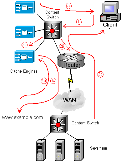
Here we have two options, an a route for cacheable content, and a b route for non-cacheable content.
The steps are as follows:
- (1) - the client request for content is intercepted by the content switch.
This request has the source IP address of the client and the destination IP address that DNS gives for the domain name
(in this case the VIP on the content switch).
- If the requested content is cacheable:
- (2a) - The content switch determines that content is cacheable and
therefore forwards the request on to one of the cache engines (depending on the configured rules).
The content switch is configured to understand that it has transparent caches as its services.
The Cache Engine is configured to transparently receive Layer 4 redirected traffic from
Layer 4-enabled content switches via MAC Forwarding (see below) so the source and destination IP
addresses are preserved. Some caches can use the Host field in the HTTP header to resolve the destination origin address.
- (3a) - On a cache miss, the cache engine forwards the request to the origin server
because it knows the IP address of the destination as it has been preserved.
- (4a) - The content is retrieved from the origin server and stored on the cache engine.
- (5a) - The content is forwarded back to the client by the CE because the source IP
address was preserved.
-
- If the requested content is not cacheable:
- (2b) - The content switch determines that the content is not cacheable, so rather
than burden the cache engines unnecessarily, the request is immediately sent out to the origin server via the router.
- (3b) - The origin server responds directly with the content.
The content switch is designed as a flow switch rather than a layer 2 switch i.e. its forwarding decisions are
based on information from layer 3 and above.
When the service is a transparent cache, the content switch MAC forwards (i.e. layer 2 switches) the HTTP Request datagrams to
the cache so that the destination IP address is not changed by the routing function of the
content switch. The cache is configured to accept frames that are destined for its own MAC address.
4.10 Smart Caching - Reverse Proxy Local to the Origin
Here the Content switch is close to the server farm. The client needs no configuration because DNS resolves to
the VIP of the content switch for this particular website:

The arrows describe the order of events if there is a cache miss:
- (1) - The client sends a DNS request to resolve www.example.com. This resolves to VIP 1
on the content switch.
- (2) - The client sends a HTTP request to VIP 1 on the content switch.
- (3) - The content switch determines that content is cacheable and
therefore forwards the request on to one of the cache engines (depending on the configured rules).
The content switch is configured to understand that it has transparent caches as its services.
The Cache Engine is configured to transparently receive Layer 4 redirected traffic from
Layer 4-enabled content switches via MAC Forwarding.
- (4) - On a cache miss, the cache engine has a rule configured that allows it to
forward the request to VIP 2 on the content switch. If there is a cache hit, then the cache forwards the content
back to the client.
- (5) - There is a content rule match on the content switch and depending on the load
balancing technique, the request is forwarded to the appropriate server.
- (6) - The content is forwarded back to the cache.
- (7) - The content is stored on the cache and forwarded back to the client.
You can host any number of domains off of one IP address.
5. Content Delivery
5.1 Operation
So far we have looked at client initiated content caching, however there are situations where an enterprise wishes to have control over
the type of content that is delivered, how it is delivered and when it should be delivered. This is a more centralised control
of content. The purpose of Content Delivery is to ease the congestion on the servers and to minimise the impact of high bandwidth
content on the network. Multicasting content is only sufficient if groups of individuals are going to see the content at the
time of the multicast. We need a way of delivering the content local to the client ready for when that client needs it.
With Enterprise Content Delivery, the organisation can manage content centrally using content management software, and
the organisation can download relevant content to remote content engines that are located close to the client.
Notice how that this is different from the client 'pulling' the content. Instead the enterprise is 'pushing' the content.
The steps required in a content delivery solution include the following:
- Develop content - PDF, video, JPG, Realmedia, Shockwave etc.
- Modify the web server to create a pointer to the content manager for the users. The web page containing
this pointer is sent to the users.
- Import media to the content manager via FTP, SMB or HTTP
- Use the manager to configure the time and locations for the delivery
- The content engines use communications technologies such as Cisco's Self Organizing Distributed Architecture (SODA)
to organise themselves in a network efficient manner.
- Replicate the appropriate content to the content engines at the scheduled times. Depending on the topology, the content
engines can participate in this replication process too.
- The user sends an HTTP Request to the Web server.
- The Web server responds with a modified page containing a URL to the content manager.
- The user now sends the HTTP Request to the content manager.
- The content engine sends back an HTTP Redirect with code 302 meaning 'moved temporarily, keep using this URL'. This
redirects the user to the nearest content engine. The 302 is required because the nearest content engine may change.
- The user sends the Request to the local CE.
- The local CE responds with the required content.
In Cisco's implementation you cannot have redundant Content Managers, however you can have up to 5 Content Routers
that are used purely to deal with HTTP Requests and send '302s' to users. The Content Routers take over from the Content
Manager should it fail. You can additionally load balance between Content Routers and Content Managers via a Content Switch.
5.2 Self Organizing Distributed Architecture (SODA)
Cisco have developed a technology that uses the idea of channels to provide a hierarchical way of distributing the requested
content. The Content Delivery Manager (CDM) is the root of the distribution tree. With SODA you can have
a different hierarchy for each media type thereby minimising bandwidth impact and storage wastage. The following diagram
illustrates how SODA works:
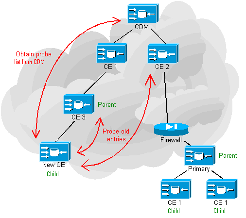
SODA operates automatically and follows these steps:
- A new Content Engine (CE) joins the network.
- The new CE starts by asking the CDM for a list of potential Parents, one of which it will choose to register with
depending on the proximity of this parent. This parent can be another CE or the CDM or Content Router (CR).
- The CE sends its actual IP address in its payload to the CDM. The CDM checks this IP address against the source IP address
of the datagram. By doing this, the CDM can decide whether or not the CE is behind a firewall or web proxy. If the CE is
behind a firewall, then a Primary is elected amongst any others that are behind this firewall and the new CE, plus
any other CEs register with the primary so that only one device is coming through the firewall. SODA and media replication
are conversations that are initiated from the CE hence why they can 'punch' through firewalls.
- The CE checks the list of potential parents which takes the form of a Probe Table. If there are any potential parents
that have not been probed in the last 5 minutes then...
- ...for each channel (media type), the CE sends a Probe. This Probe is about 1KB in size and checks for TCP setup time,
HTTP and CGI execution time etc.
- The receiver of this probe delays responding. Tha amount of delay is dependent on the replication bandwidth that it is
allowed to use, and is also dependent on the type of the device receiving the probe. A CDM would want to discourage
Child CEs from registering with it if at all possible, since it is the hub of each SODA tree.
- The receiver responds to the new CE and the new CE caches the probe times for 45 minutes.
- The new CE tries to register as a child with the device that has the fastest response times.
- If this potential parent has any children, then the new CE will obtain a list of candidate parents from this CE and start
the process again from step 2 above. Slowly but surely the new CE steps down the hierarchy until it finds the most
optimal place in the tree. Remember that this process occurs for each channel to which that CE is subscribed!
- Once the parent-child relationship has been established, the child sends the parent an HTTP GET Keepalive
every 30 seconds indicating its health. The parent does the same to its own parent and includes the status of all of its
children.
A good idea to make this SODA process scalable, is to surround the CDM with a number of CEs which become the immediate
children of the CDM. All other CEs then register with those CEs and thereby minimise the risk of overloading the CDM.
Each Content Engine can be assigned to Coverage Zones whether Preferred or Regular. The Preferred
Coverage Zone is given by the subnet in which that CE resides. This makes sense since the CDM can detect which coverage
zone has been configured on which CE. You can configure a Regular Coverage zone on a CE, say CE1, which acts as a backup for
a CE, say CE2, that exists in another 'nearby' subnet. CE2 would have that that zone as its Preferred
Coverage zone. If CE2 failed, the CDM would know (via the keepalives) and CE1 would take over and service requests for the content.
If there are multiple CEs in a coverage zone, then the CDM randomly assigns HTTP Requests to them.
5.3 File Replication
Once the SODA hierarchy is in place for each channel, efficient media replication can occur by each CE 'pulling' the content from its parent.
The CE SODA Librarian is a database that contains all the channels that the CE is subscribed to. The master database is kept
in the CDM and every 3 minutes the CEs synchronise with this, through the SODA hierarchy.
Once replication starts for a particular media file and a CE starts to receive the file, a child CE can immediately begin
to pull this file even though the parent CE may not yet have the complete file. This speeds up the replication process.

|
